Sound Effects Box Instructions

Don’t have this fun kit yet? Buy one here – Sound Effects Box.
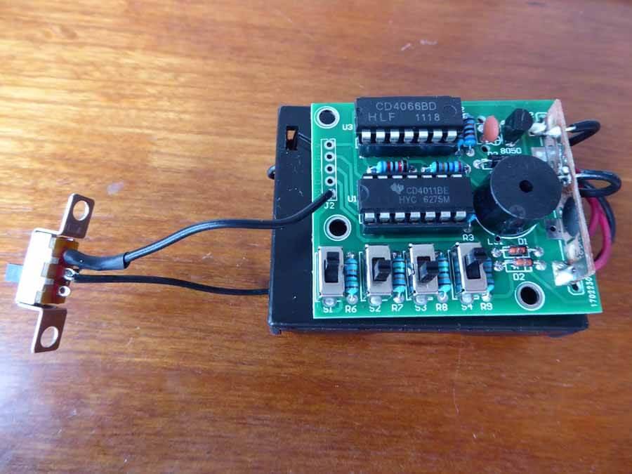
Parts List
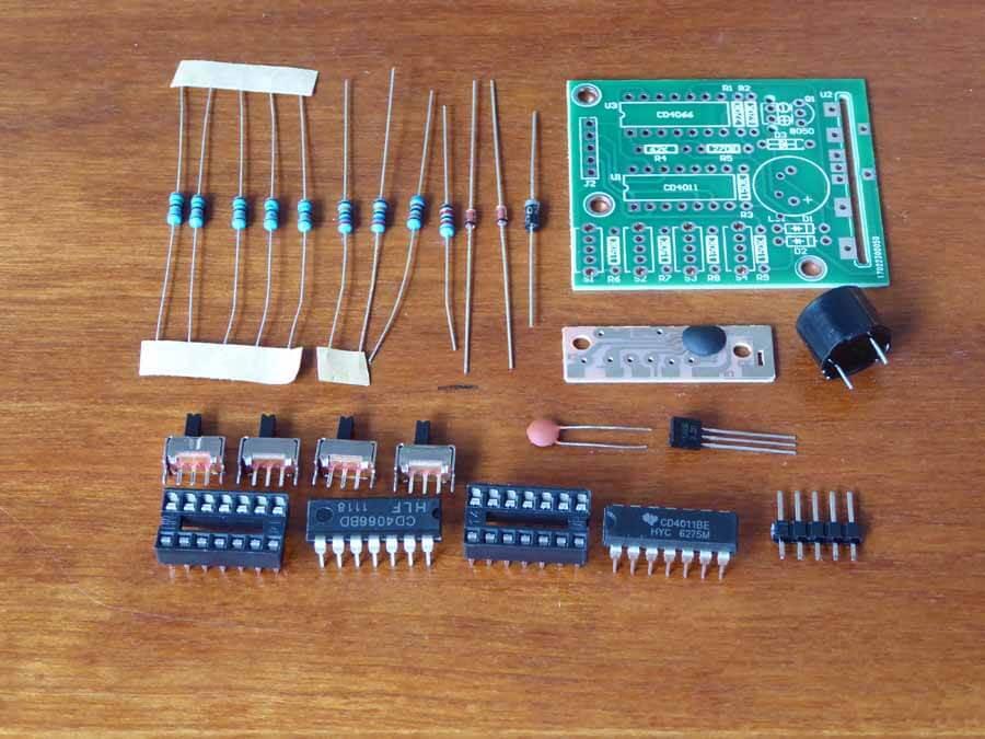
9 resistors – 5 150k, 1 62k, 2 270k, 1 620k
4 switches
2 ICs CD4011BE, CD4066BD
2 IC Sockets
1 ceramic capacitor 104
1 transistor S8050
3 diodes – 2 IN4148, 1 IN4007
5 header pins
5V speaker
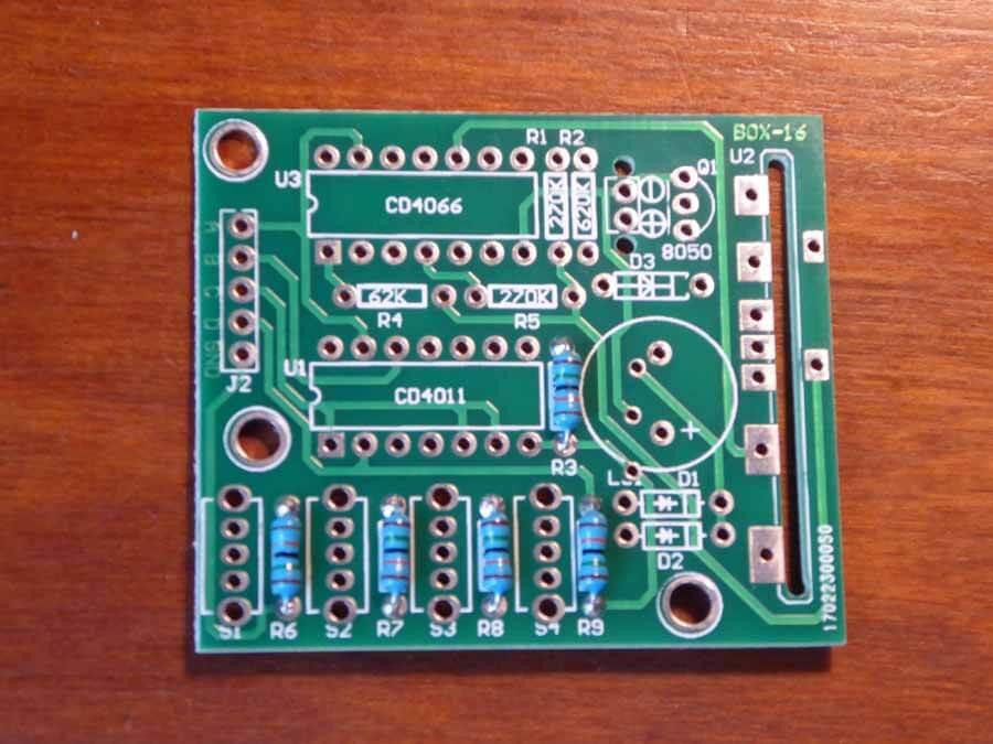
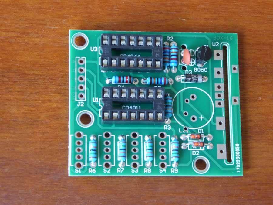
Solder the low profile items first.
Start with the 5 150k resistors marked R6 – R9 and R3.
Orientation does not matter for resistors.
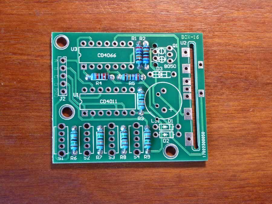
Next solder the 2 270k resistors marked R1 and R5 on the board.
Next up is the 62k resistor marked R4 on the board. Be careful here as it looks almost exactly like the 620k resistor. The 62K resistor is blue, red, black, red, brown.
The 620K resistor is blue, red, black, orange, brown. Solder this one next, marked R2 on the board.
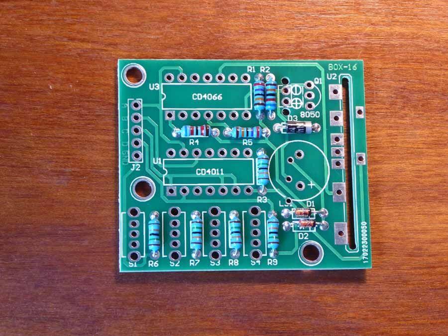
Next add the single IN4007 diode with the band facing the outside edge. It is marked D3 on the board. Remember orientation does matter for diodes.
Now solder the remaining 2 diodes marked D1 and D2 on the board.
Now attach the two IC sockets labeled U1 and U3. Note the notch for orientation.
Now solder the capacitor and transistor.
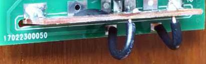
Now solder on the extra PCB, then the two backside wires. This may take a few minutes. Orient the tan pcb so black blob is on diode side, not transistor side. Line up the silver connections and use masking tap or painter’s tape to temporarily hold it in place. First solder one of the end connections to hold it in place and then flip it over to solder the remaining 5 connections. It is easier to solder most of the joints from the bottom.
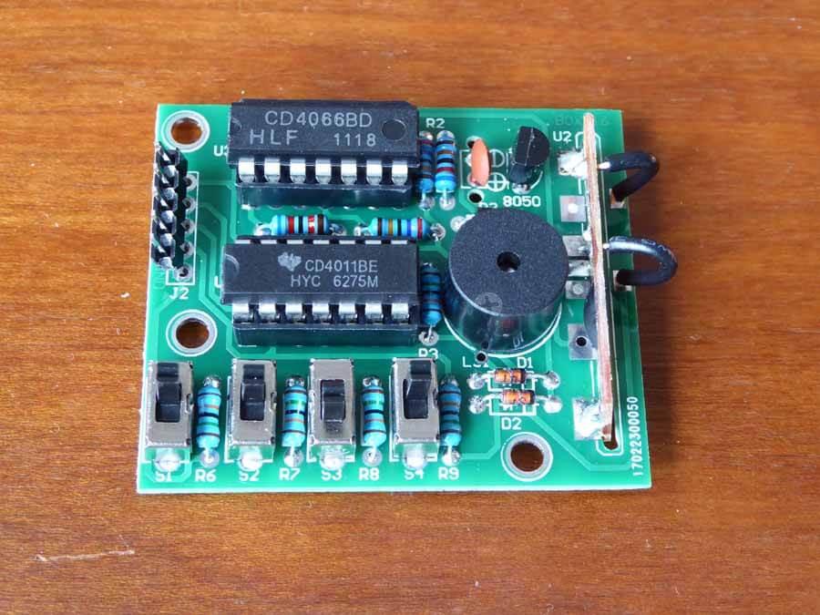
Solder all 4 switches and then the speaker. Watch out for the polarity of the speaker. One side should have a “+” symbol on top.
Now put in the IC chips. Each one is labeled with it’s part number and make sure to orient it so the cutout on the chip matches where the notch on the holder is.
Now the only thing left is power.
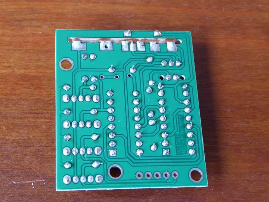
The red or positive wire goes to the end pad to the right of the black blob on the standup pcb. The black or ground wire goes to the hole marked GND near the two ICs.
Another option is to solder on the included 5 pin header and then solder the ground wire to a female header. This would easily allow you to remove or apply the ground wire, thus turning it on and off. Or you could solder just the “+” or red wire and leave the ground wire loose to leave it off until you want some noise and then just hold it in place.
Happy soldering and noisemaking!