In this how to we will show you how to make a Turtle Robot from DFRobot. The robot is programmable through the Arduino IDE or it can be controlled via Bluetooth. You will need the complete Turtle Kit , a small phillips & flathead screwdrivers, 5 AA batteries. Optional is a smartphone for Bluetooth control and the bluetooth app GoBLE.
Software
To start, you should get your software setup first. You will need the Arduino IDE and the Metro library. The Servo library is already included in the Arduino IDE. Download Turtle Kit examples and the Metro library here.
Make sure you put the Metro library in your Arduino/libraries folder.
You will also see two more examples you will need called Platform and URM37andServo.
URM37andServo will test only the servo, where as the Platform example will test the whole robot. We also suggest using a file called MotorTest that just tests the motors. You should take all three files, MotorTest, URM37andServo and Platform and put them in a folder called something like Turtle Bot. Then put the Turtle Bot folder inside your Arduino folder.
Now open the Arduino IDE and make sure you can access the example files.
Once this is set up and working, you can go on to building the robot base.
Platform Setup
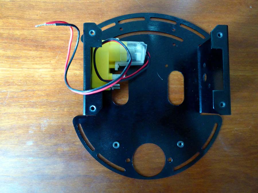
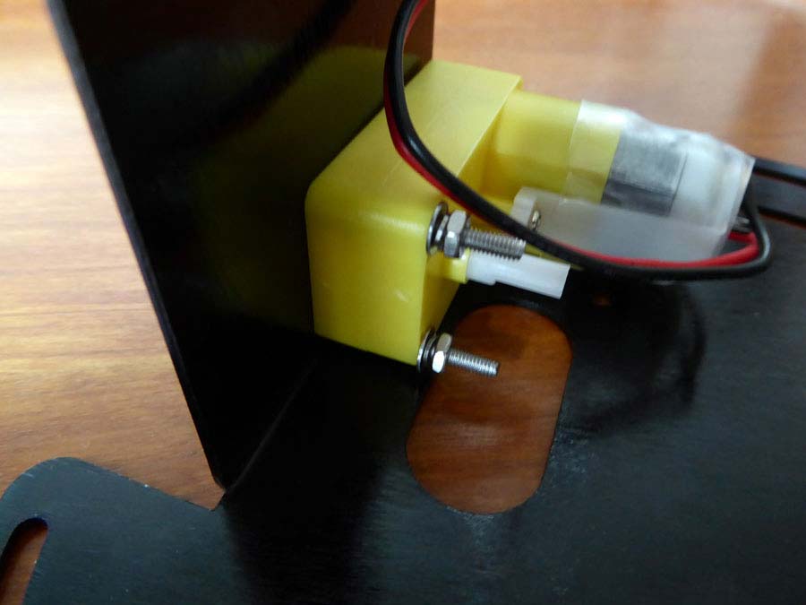
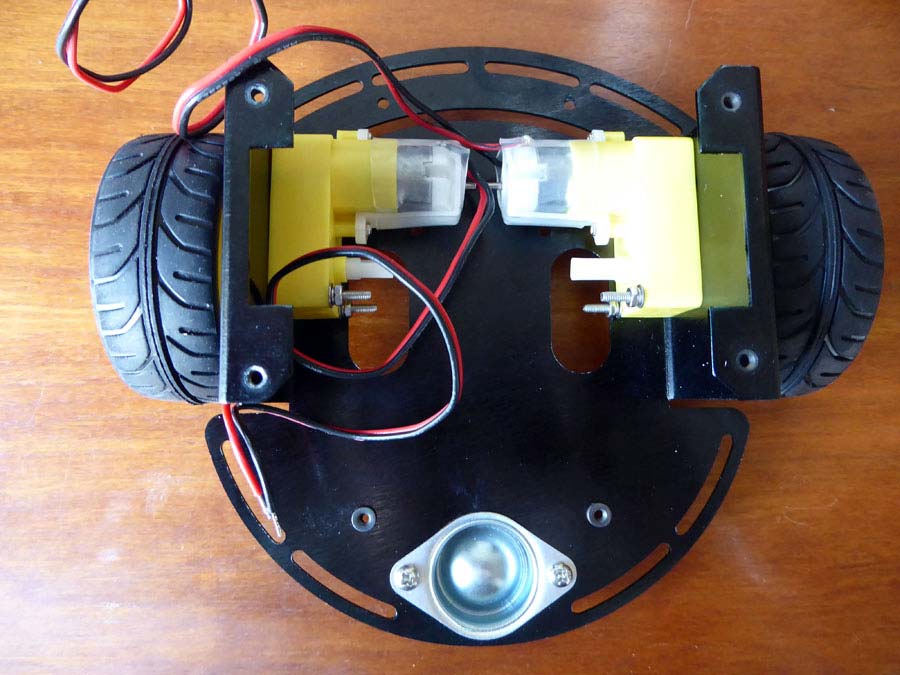
Now we can start setting up the robot base. First we will take the bottom plate and add the two motors. Use the longer A4 screws along with the regular washer, the locking washer and the nut . Attach the first motor as shown in the photos below.
Now attach the second motor in the same manner as shown in the photo below.
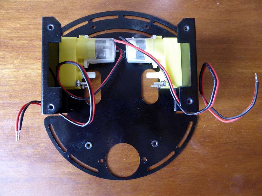
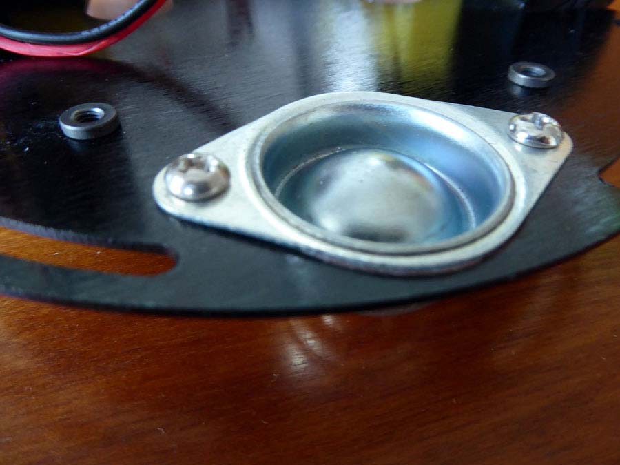
Now add the caster to the front of the platform with the A5 screws and nuts. Then go ahead and push the wheels on to the nubs sticking out from the motors.
Your robot should now look like the photo below.
Now let’s add the sensor mounting grill with the A6 screws and nuts.
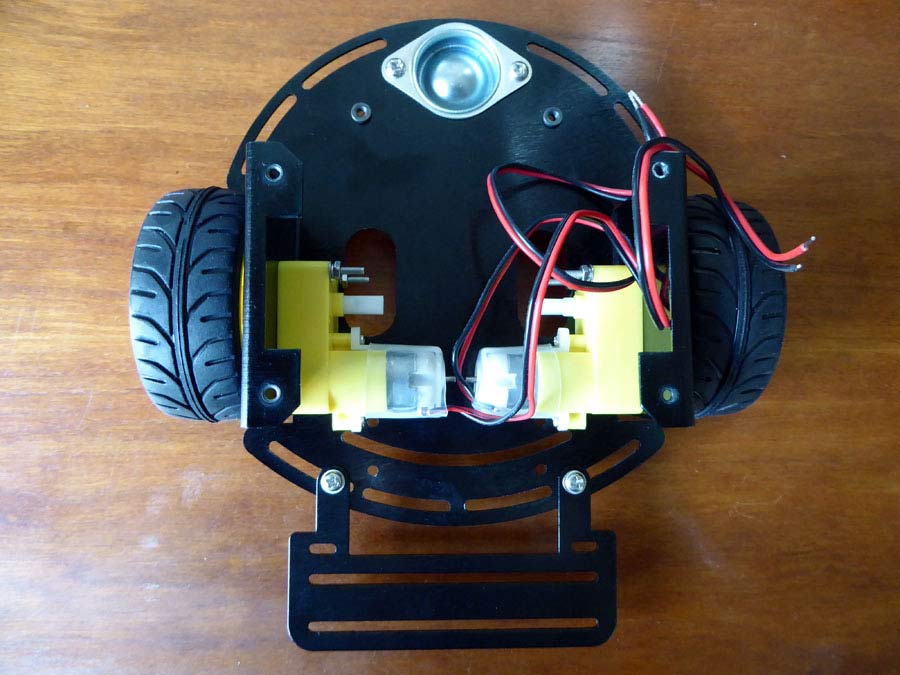
Now we will add the battery holder with only the A7 flat head screws.
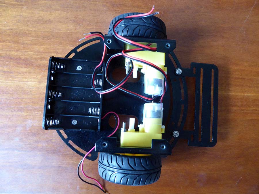
Set this aside and we will now work on the top plate.
In the kit they give you an on/off switch and a power plug. We attached them as we may want them for future use but you do not need them to make the robot work.
Screw a nut and special locking washer onto the switch top. Insert the switch from the bottom of the top plate and attach it with another nut. Use a washer and nut to attach the power plug.
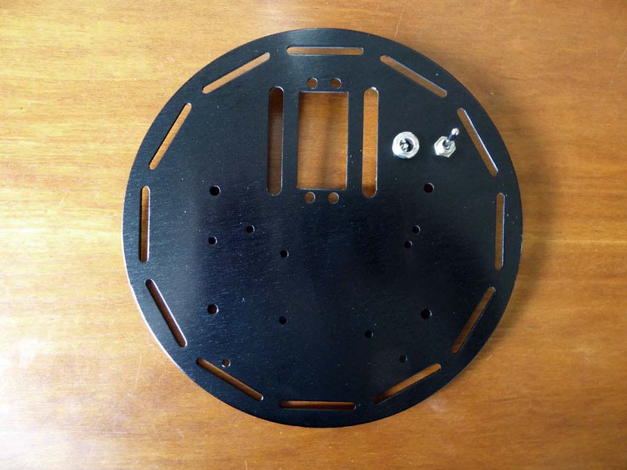
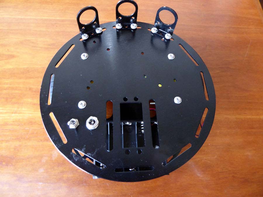
You also get 3 sensor brackets but they are also not needed now. You can attach them later if you add more sensors. You can see them in the image below.
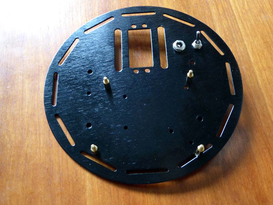
Now we need to attach the stand offs to the top plate. This will keep the main ROMEO BLE board from touching the top plate.
Attach the standoffs with a screw on the bottom in the configuration shown below . Test fit the ROMEO BLE board to make sure it fits onto the standoffs.
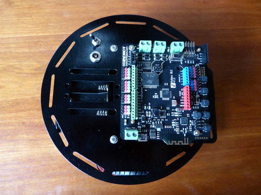
Here is what the ROMEO BLE board looks like when attached to the standoffs. Don’t attach the board just yet though.
Now Attach the top plate to the bottom chassis by using 4 screws as shown below.

Next attach the board to the standoffs.
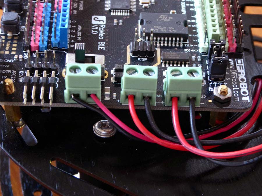
Now feed the motor and battery holder wires up through the middle hole closest to the power plug. Using the flathead screwdriver, connect motor the wires to the green plugs labeled M1, M2 and the battery holder wires the the third plug next to the on/off switch. Make sure the switch is off.
Also make sure you have the motor selection pins on the correct positions.
For mine I put the selection jumpers on E1 and E2 to get it to work. See corner of the board below the DFRobot logo.
At this point you can plug the board into your computer and upload the motor test code. You should see the wheels spin slowly forward. The caster side of the robot is the front. Now unplug the board from your computer.
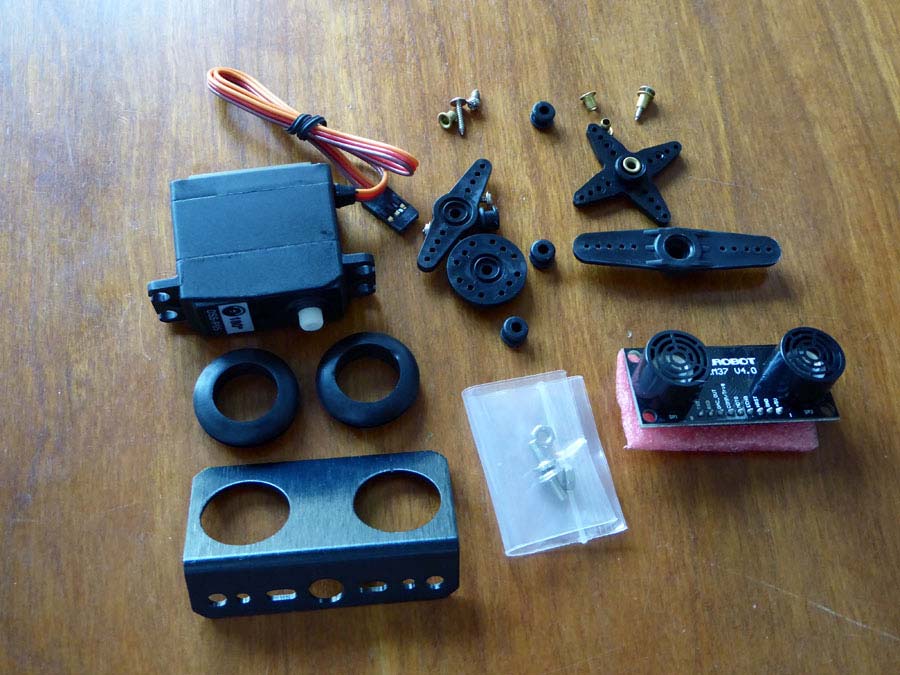
Servo & Sensor
Next we will work on the servo motor and sensor.
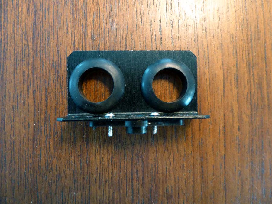
First we want to insert the rubber rings onto the servo bracket.
Then take the long rectangular servo horn and screw the sensor bracket onto it. On the sensor bracket, use the longer holes on either side of the large center hole.
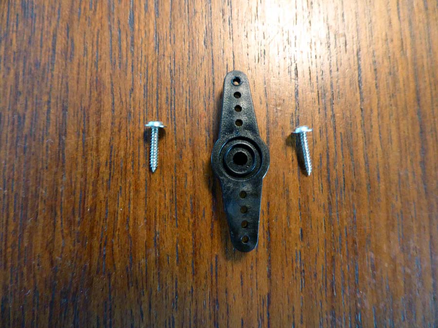
One extra note is that we used a Dremel tool to file down the ends of the screws to make sure they had enough clearance over the servo. This is most likely not need, just an extra precaution.
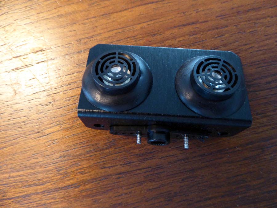
Now insert the sensor from the backside. Don’t be afraid to push a little hard to get it into the rubber rings. You should now have something like the image below.
Mount Servo
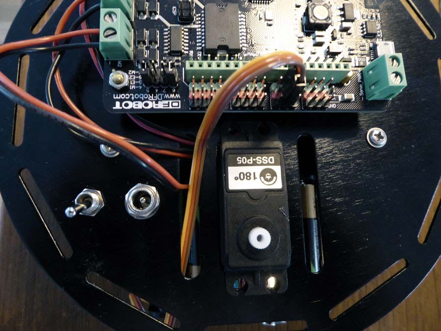
Insert the servo motor into the rectangular hole above the battery holder. Screw it into place using the A6 screws. There are 4 screw holes but we only used the 2 in front as the back ones were too hard to reach.
Then thread your servo wires up through the same hole you used for the motor wires. Attach the wires to the column 4th from the left. Brown goes to ground, red goes to power and yellow goes to green.
Sensor
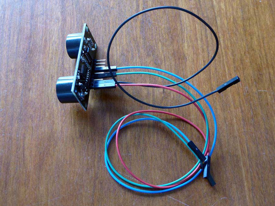
Now you will need 4 hookup wires. Get a blue wire and attach it to the COMP/TRIG pin on the sensor. Attach a green wire to PWM, a black wire to ground or GND and a red wire to power or +5V.
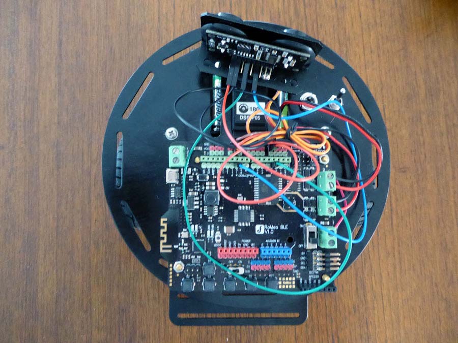
Push the sensor onto the plastic nub sticking up from the servo with the sensor facing forward. Connect the blue wire to pin 10 and the green wire to green pin 3. Then connect GND to black pin GND and +5V to red pin PWR.
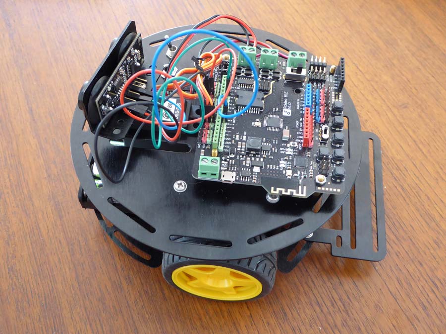
Your robot should now look like the one below. If have a twist tie you could tidy up the wires a bit.
Now go back to your computer and open the servo test sketch. Now plug the robot into your computer but be careful. You will need to pick up the robot as you should still have the motor test sketch installed. You could also place the robot on a book or piece of tupperware to get the wheels off of your table or desk. Upload the servo sketch and test it. If it is not moving, double check your wiring.
You may also need to adjust the mounting of the sensor so that it is sweeping the same amount on the right and left sides.
Once this is done you are ready to install the complete code. Upload the Platform code to the robot and disconnect it from the computer. Add your five AA batteries, place it on the floor and turn it on. Does it go forward? Congratulations you have built a robot!
Now the code supplied is only example code and will need some adjusting.
We suggest you start by making a copy of the Platform code and renaming it then play around with modifying this section of code as a start.
if(actualDistance <= 30){
myservo.write(90);
if(pos>=90){
carBack(50,50);
// Serial.println(“carBack”);
delay(100);
carTurnRight(70,70);
// Serial.println(“carTurnRight”);
delay(300);
}else{
carBack(50,50);
// Serial.println(“carBack”);
delay(100);
carTurnLeft(70,70);
// Serial.println(“carTurnLeft”);
delay(100);
}
}else{
carAdvance(100,100);
// Serial.println(“carAdvance”);
delay(100);
}
Extras
DFRobot suggest adding an extra power supply for just the servo motor, so I did that as I had one. I wired up the switch they gave us to a 5 AA battery pack. Keep in mind they servo needs 4.8 – 6 V power. I tested my battery pack and since they were not fully charged I was at 5.5 volts, so good to go.
The GND wire goes directly from the battery pack to GND on the green servo terminal. The red positive wire goes to one end pole on the switch . Another red wire goes from the middle pole on the switch the the positive servo terminal. I soldered the wires on and added heat shrink for protection.
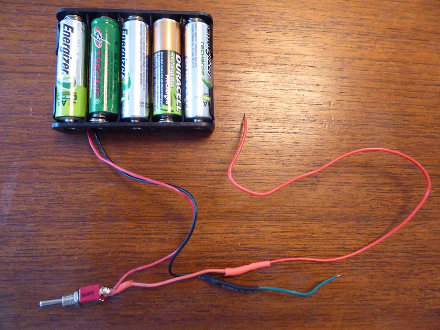
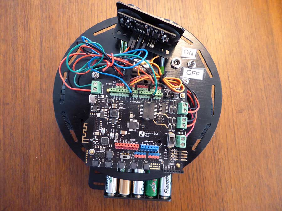
After screwing the switch back in place and connecting the servo terminal wires I added some on/off labels around the switch.
Bluetooth / Smartphone Control
Get the code and libraries needed on Github. Make sure to put the libraries in your Arduino library folder.
Download the GoBLE app for your iPhone.
Open the code called GoBLE_APP in Arduino and upload it to your board. Unplug the board from your computer and turn it on. Open the GoBLE app on your and it should pair automatically. If it doesn’t, look for a Bluetooth connection called Bluno.
Once connected use the circle on the left like a joystick.
One final extra we added was a costume. Since our robot was being used in our kitchen we added a toque or chef’s hat and a spoon so the robot could help us cook.
Have fun with your new robot!